by Carol Fey
Wiring diagrams made simple:
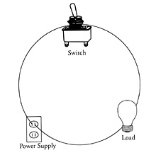
Figure 1
It’s always great when there are more pictures than words, right?
Except when those pictures are wiring diagrams. Do you know
how to read a wiring diagram? If you don’t, you have a lot of
company. Most people don’t — even people in the heating business.
Wiring diagrams can look complicated. But if Figure 1 were your
wiring diagram, you could easily read it. The fact is, a “real”
wiring diagram can be nearly as easy once you learn what the
pictures (symbols) mean. A wiring diagram is just pictures!
And all of those lines are just connecting pictures together.
Back Row Boys, this was made for you. A wiring diagram is made
of circuits. Each circuit — no matter how simple or complex
— is made up of a power supply, a load, and one or more switches.
“What about all those other things?” you may wonder. “What about
valves, thermostats, limits, zoning panels?” Every one of those
is either a power supply, a switch or load. Let’s try an animal
analogy. There are endless types of dogs: collies, labs, spaniels,
mongrels, etc. How are you going to classify them? If your only
classifications are dogs, cats and birds, you don’t have to
worry about it. They’re all dogs. The same is true for controls.
It doesn’t matter for now if it’s a thermostat, a limit or a
relay terminal — they’re all switches. Dogs behave like dogs,
not like birds. Switches behave like switches, not like power
supplies. There are three types of symbols in a wiring diagram:
power supplies, switches and loads. Let’s start with the power
supply.
Power Supplies:
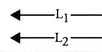
Figure 2
There are two different types of power supply: line voltage
(usually 120V) and low voltage (24V). Boilers, furnaces and
air conditioners run on line voltage. Their controls usually
run on low voltage. There’s a different symbol for each type.
Figure 2 is the symbol for a line voltage power supply. It’s
easiest to just accept this as the symbol for where line voltage
comes from, and let it go at that. But many of us want to know
a little more. So here’s what this symbol is about. There are
two arrows pointing in the same direction. What are they pointing
to? Intuitively, we want them to point a direction for the electricity
to go. But if you try to make sense out of that idea, it just
doesn’t work. I’ve asked many engineers and no one knows for
sure why that symbol is the way it is. My electrical engineer
buddy, Mike, said he never thought about it — that’s just the
way it is. But when pressed about what it might be, he said
he thinks the arrows represent the male side of a connection.
They’re like the plug on the end of the toaster cord; they show
where the circuit plugs in. But plug into what? Before I got
Mike’s conjecture, I made up my own explanation. It works, too.
Those two arrows are pointing to where the electricity comes
from — the power plant. In real life, the connection is simply
going to be to where electricity enters the building. Sometimes,
but not always, the two lines from the arrows have “L1” written
on one, and “L2” on the other. L1 is the “hot side” or “hot
leg.” L2 is “neutral.”
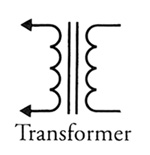
Figure 3
Even though they’re not always labeled, in real life it can
be important to know the difference. L1 is the wire that can
hurt you, and L2 isn’t. The switch in the circuit (Figure
3) should be placed in the L1 leg because we need to be able
to turn off the hot electricity before it gets into the circuit.
If the circuit is low voltage (24V) rather than line voltage,
the power supply will be a transformer. Notice that the two
arrows are still there from the line voltage symbol. That
side of the transformer is connected to line voltage. The
left side of the transformer is low voltage (magically “transformed”
inside the transformer). This second side is called the “secondary,”
and it is the source of electricity for a low-voltage circuit.
Switch:
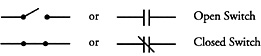
Figure 4
The second symbol found in a circuit is a switch. Figure 4
shows symbols for a switch. A switch may be shown either “open”
or “closed.” Open is just like a drawbridge. That means it’s
off, because there’s no path for the electricity to go on.
Load:
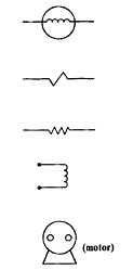
Figure 5
A load is the third and final part of a circuit. A load makes
it difficult for the electricity to pass through. Thus the
symbol for a load usually is some sort of squiggle, symbolizing
that there is resistance to the electricity’s passing through.
This resistance, of course, is what changes electricity into
another form of energy, such as heat, light, motion, sound
or magnetism. Figure 5 shows symbols for loads. When the load
is a motor, you just have to imagine the squiggle inside it.
When we put the three symbols together with lines, we have
a complete circuit.
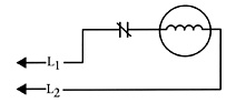
Figure 6
Figure 6 shows the same thing as the picture of the light
bulb circuit at the beginning of this column.
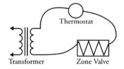
Figure 7
Figure 7 is a low-voltage circuit where the transformer is
the power supply, the thermostat is the switch and the zone
valve is the load. More on circuits and diagrams coming soon!
Fey at ISH North America:
Carol Fey was a scheduled speaker at a past year's ISH North
America trade show (http://www.ish-na.com/) held in Boston. She presented
“The Fun & Effective Way To Teach Controls Wiring To Your
Employees”. |